
Starting out with the Raspberry Pi can be an exciting experience. It’s never been easier for a beginner to get started with both coding and DIY electronics.
One easy project is to make a simple circuit with two LEDs and control one of them using code. Here’s how to do it!
Required Components
Before starting, you’ll need to make sure you have an operating system on your Pi. Installing Raspbian via NOOBS is by far the quickest way to get going.
Boot up your Pi, and attach it to a screen, mouse, and keyboard like a regular desktop computer. Alternatively, you can connect to your Pi via SSH to save the clutter of extra wires. We will cover how to control LEDs whichever method you choose.
Once you are sure the Raspberry Pi is booting up correctly, turn it off again while you build your circuit, to avoid damaging your Pi.
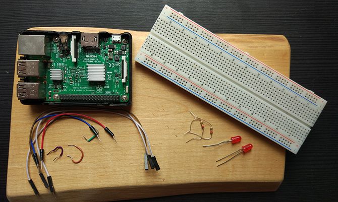
Along with your Raspberry Pi, you will need:
- A breadboard
- 2 x LEDs
- 2 x resistors (anything from 220 Ohm to 1 kOhm)
- Hookup cables
If you got your Raspberry Pi with a starter kit, you will likely already have everything on this list. Now let’s build our circuit.
A Simple LED Circuit
Set up your components as shown in this Fritzing diagram:
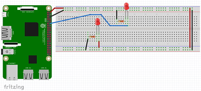
This circuit does two things. The 5v and GND pins of the Pi attach to the Power Rails of the breadboard.
Note: To get a better idea of what the breadboard is and how it works, take a look at our breadboard crash course.
The two power rails are linked at the end, and a line runs from the positive power rail into the positive (anode) side of the bottom LED. The negative side of the LED is attached to a resistor, which is connected back to the GND power line.
The top LED is wired up differently. A line runs from pin 12 (GPIO18) of the Raspberry Pi into the positive side of the LED, which runs through the resistor and back into the GND rail. Pin 12 is also GPIO18, as confusing as that sounds, our guide to Raspberry Pi GPIO pins will help clear things up!
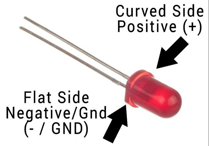
It isn’t important which way round you set up the resistors, but it is essential to get the LEDs the right way round. Luckily, it is easy to tell which side is which:
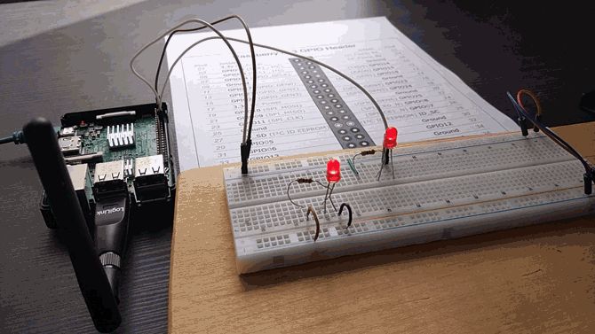
Once you have everything set up it should look something like this:
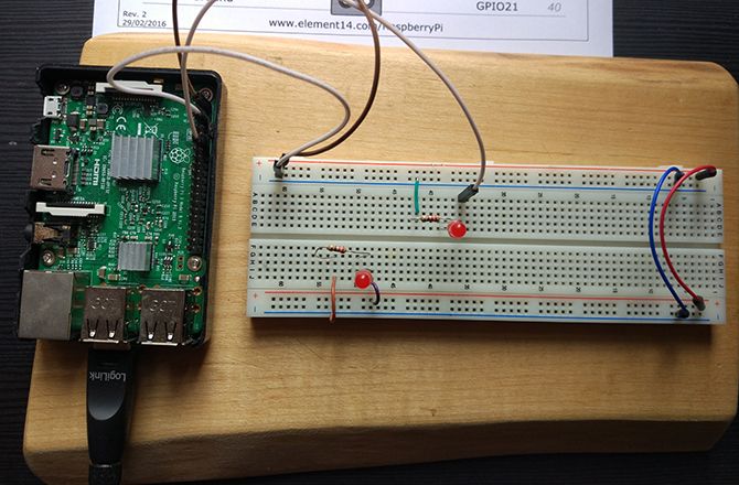
Note that I am using an external Wi-Fi dongle here, it’s only needed if you suffer from the curse of the weak Wi-Fi!
Make sure everything is set up correctly, then boot up your Raspberry Pi. The LED attached directly to the 5v pin should turn on immediately. The other LED is the one you will control from code.
Method 1: Python via IDLE
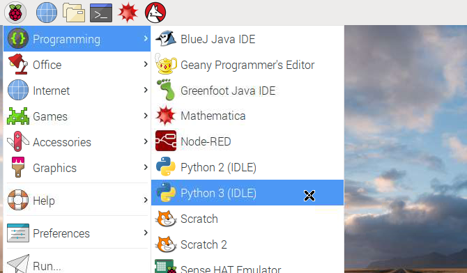
If you are using your Raspberry Pi in desktop mode, open the applications menu in the top left of your screen, and navigate to Programming > Python 3 (IDLE). This will open the Python shell. If you are using SSH mode, instructions are provided later in the article.
The Raspbian operating system comes with Python already installed. Python is a perfect programming language for beginners, and there are many great websites out there to help you get started. We will create a short Python together, though if you’d rather grab the finished script you can copy the code from Pastebin.
You could program directly into the shell, but it would be nice to create a program you can save and use again. Open a new file by clicking File > New File.

You are going to create a simple blink sketch which will turn the LED on and off. To begin, you need to import the RPi.GPIO and time modules.
import RPi.GPIO as GPIO
import time
Importing as GPIO saves you from typing RPi.GPIO every time, and you will need the time module for the delays between the LED turning on and off. Now, set up the GPIO pin.
GPIO.setmode(GPIO.BOARD)
GPIO.setwarnings(False)

ledPin = 12

GPIO.setup(ledPin, GPIO.OUT)
Set up the GPIO pins to use BOARD numbering and set GPIO warnings to false. Don’t worry if you do not understand this at this stage! Next, set your ledPin to be pin 12 (GPIO18) of your Pi. Finally, set up the ledPin to OUTPUT. Now the pin is ready to control the LED.
Making the LED Light Flash
By creating a for loop, you can control the number of times the LED flashes. Enter the following code, making sure to indent it the same way.
for i in range(5):
        print("LED turning on.")
        GPIO.output(ledPin, GPIO.HIGH)
        time.sleep(0.5)
        print("LED turning off.")
        GPIO.output(ledPin, GPIO.LOW)
        time.sleep(0.5)
This for loop runs five times, and each time it will print to the Python Shell what it is doing, before changing pin 12 to HIGH, turning the LED on, then LOW, turning the pin off. The program then quits automatically.
Save your program, and then select Run > Run Module from the editor menu. Your LED should flash five times!
Congratulations! You have created your first GPIO program!
Method 2: Python via SSH and Nano
If you have connected to your Raspberry Pi via SSH, you can create this program from the command line. Create a new script in Nano by typing:
sudo nano blink.py
This will open up a new file in the Nano editor called blink.py. Enter the same code as above, making sure to indent everything correctly, and save the program by pressing Ctrl-X. This triggers a save prompt at the bottom of the screen.
Type y to save it, and enter to confirm the filename. This will bring you back to the command line. You can run your program using the Python command:
python blink.py
You should see the LED flash and the print function on the screen.

Dive Deeper With More Raspberry Pi Projects
Learning how to control LEDs using code is an important first step in your DIY education. This level of coding is all that you need for many Raspberry Pi beginner projects.
As well as being great for homemade electronics, the Raspberry Pi is capable of a vast array of different things, and working through our awesome Raspberry Pi guide will help you get to grips with the many uses of these tiny computers.
Read the full article: How to Program Your Raspberry Pi to Control LED Lights
Read Full Article
No comments:
Post a Comment